Resistors, those unsung heroes of the electronics world, play a vital role in regulating current flow. Understanding how to decipher their values, whether by type or colour coding, is a key skill for any electronics enthusiast. In this guide, we’ll explore the nuances of resistor identification, accompanied by a cheeky mnemonic for memorisation.
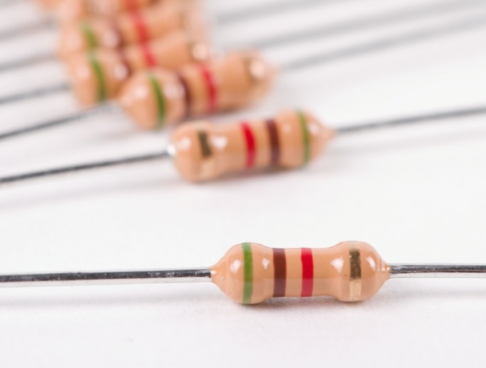
1. Recognising Resistor Types:
Before diving into the world of colour bands, it’s crucial to know the types of resistors you might encounter:
- Fixed Resistors: Steady as a cup of tea, these resistors maintain a constant value.
- Variable Resistors (Potentiometers): The chameleons of the electronic world, allowing you to adjust resistance on the fly.
- Specialty Resistors: These quirky characters, like thermistors and photo-resistors, bring their unique traits to the circuit party.
2. Reading Resistor Colour Codes:
1. Identify the Bands: Resistors typically have four or five colored bands.
2. Determine the Direction: Hold the resistor with the Gold, Silver, or Red band (if present) on the right side.
3. Read the Bands from Left to Right: The first two bands represent the significant digits, the third band represents the multiplier, and the fourth band (if present) represents tolerance.
3. Colour Coding for Four-Band Resistors:
Four-band resistors use a colour code system to convey their resistance values and tolerance. The bands typically represent:
- First Band (1st Significant Figure): The initial digit of the resistance value.
- Second Band (2nd Significant Figure): The second digit of the resistance value.
- Third Band (Multiplier): Indicates the power of 10 by which the first two digits are multiplied.
- Fourth Band (Tolerance): Denotes the tolerance or the permissible percentage variation from the nominal resistance.
To make this more memorable, let’s introduce a humorous mnemonic: “Bad Boys Race Our Young Girls, But Vicky Gets Wed.” This is only an example of one mnemonic, there are different varieties of mnemonics to help you remember the colour coding. The colour coding is a global standard.
This quirky phrase corresponds to the order of the bands: Black, Brown, Red, Orange, Yellow, Green, Blue, Violet, Grey, White.
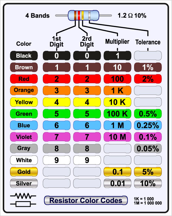
For instance, if you encounter a resistor with Yellow, Violet, Red, and Gold bands:
- Yellow (1st Significant Figure): 4
- Violet (2nd Significant Figure): 7
- Red (Multiplier): (102)=(100)
- Gold (Tolerance): ±5%
So, the resistor’s value is (47 x 100 Ω = 4700 Ω Or 4.7 KΩ) with a tolerance of ±5%.
4. Colour Coding for Five-Band Resistors:

Five-band resistors include an additional band for precision. The order remains the same.
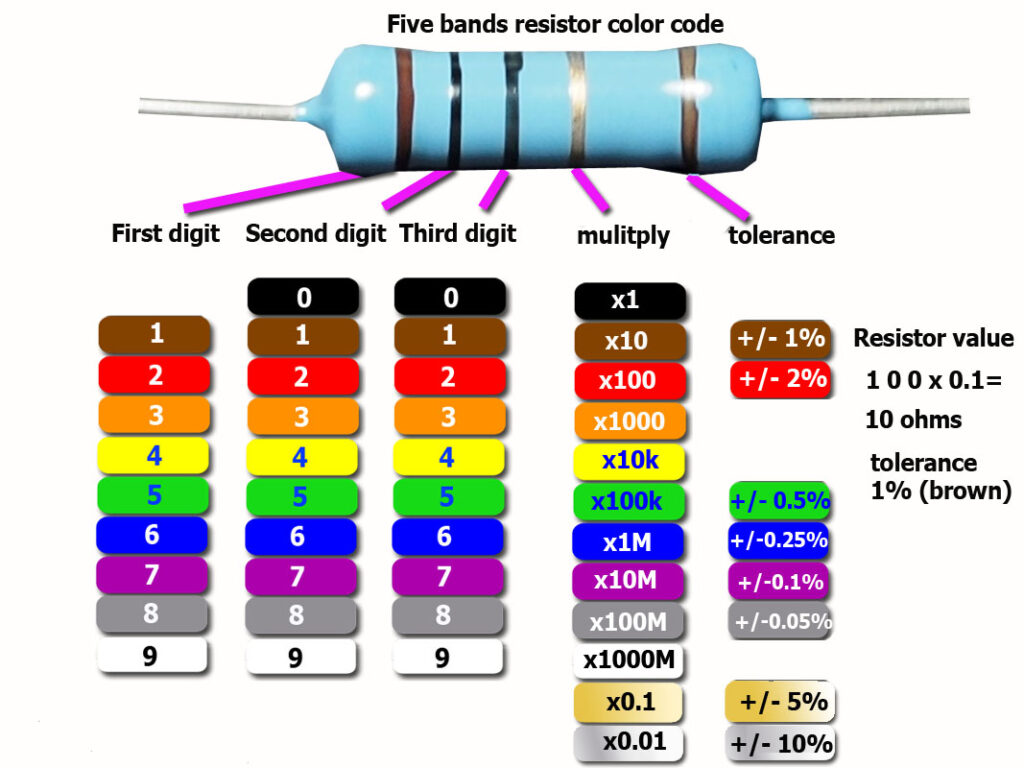
As we said there’s different varieties of mnemonics to help you memorise the colour codes, here’s two more: with a bit British humour: “British Birds Rock Our Gardens, But Vicky Grows Wiser.”
Or: “Bye, Bye Rosie Off You Go Bristol Via Great Western“.
The other way that resistors can be coded is by using BSEN 60062 (previously BS1852). With this type of coding, the value of the resistor is printed on the component and the multiplier is the same as it would be when we are using standard notation. The only extra thing to remember is the way that the tolerance is recorded.
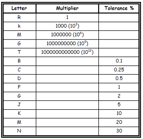
The position of the first letter tells you where you need to place the decimal point.
We’ll look at one or two examples.
1/. R22J R22J = 0.22Ω ± 5%
2/. 2k2G 2k2G = 2200Ω ± 2%
3/. 470kJ 470kJ = 470000Ω ± 5%
4/. 3R9K 3R9K = 3.9Ω ± 10%
Notice the positioning of the decimal point!
Have a look at the following codes.
1/. 4.7MΩ at 10% tolerance 4.7MΩ = 4M7K
2/. 1.2kΩ at 5% tolerance 1.2kΩ = 1k2J
3/. 330Ω at 2% tolerance 330Ω = 330RG
4/. 1.5Ω at 1% tolerance 1.5Ω = 1R5F
5/. 82kΩ at 5% tolerance 82kΩ = 8k2J
For the following resistor colour codes convert them to BSEN60062 form.
a). Red; Red; Red; Gold.
b). Brown; Black; Grey; Silver.
c). Yellow; Violet; Orange; Red.
d). Grey; Green; Black; Orange; Gold. [Notice the change to five-band resistor here]
e). Orange; Red; Black; Brown; Red.
To see if you have answered them right go here.
Capacitor Colour Coding:
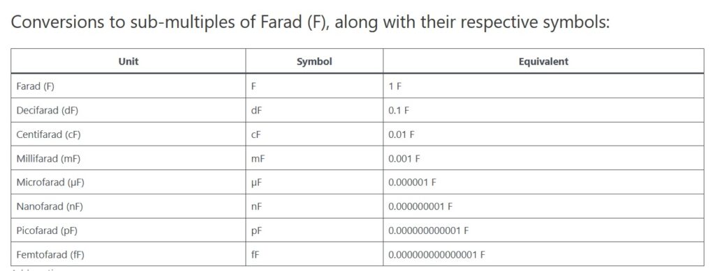
Capacitors store and release electrical energy in circuits. Unlike resistors, capacitors usually have a numerical code written on them. In the case of electrolytic capacitors the value is stated with the unit and the working voltage, but in non-electrolytic / non-polarized capacitors, their value is written in a way that the last digit always indicates the number of zeros similar to resistors, and the unit is in Pico Farad unless stated otherwise.. For example if the value reads “473”, it means the value of the capacitor is a 47 Pico Farad. However, there are capacitors with colour coding, the same as resistors, these are usually polymer capacitors. Here you can learn how to read the capacitor colour coding;
Reading Capacitor Colour Codes:
- Identify the Bands: Capacitors typically have two to three coloured bands.
- Determine the Direction: Similar to resistors, orient the capacitor with the tolerance band (if present) on the right side.
- Read the Bands from Left to Right: The first two bands represent the significant digits, and the third band (if present) represents the multiplier.
Note: Remember the value you find by colour codes or written on capacitors if NOT specified is in “Pico Farad”.
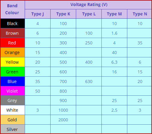
Example 1:
Let’s decode a capacitor with the bands: Yellow, Violet, Red.
- Yellow: 4
- Violet: 7
- Red: Multiplier of (102)or (100)
So, the capacitance value is 47 x 100 Pico-Farads, which equals 4700 Pico-Farad or 4.7 Nano-Farad.
Example 2:
A ceramic capacitor has the number 273 written on it, whats its value?
The first two digits are the first two significant numbers and the third digit is the multiplier, and it’s always written in Pico-farad unit, so the value of the capacitor is 27000 Pico-Farad, or 27 Nano-Farad.
Conclusion:
Understanding resistor and capacitor color coding is essential for working with electronic circuits. Practice decoding various components to become proficient. Always double-check your readings to ensure accuracy in your circuit designs.


