Introduction
Photodiodes are semiconductor devices that convert light into electrical current. They are widely used in various applications including light sensing, optical communication, and photovoltaic systems. This article delves into the operation of photodiodes, their biasing methods, photodiode arrays, and examples of photodiode circuits.
Operation of a Photodiode
A photodiode operates based on the photoelectric effect. When photons of sufficient energy strike the semiconductor material, they excite electrons, creating electron-hole pairs. This generation of charge carriers leads to a current when an external circuit is connected.
Photodiodes are typically made from silicon, though other materials like gallium arsenide (GaAs) and indium gallium arsenide (InGaAs) are also used, especially for applications requiring sensitivity to different wavelengths of light.
Biasing of Photodiodes
Photodiodes can operate in two main modes: photovoltaic mode and photoconductive mode.
- Photovoltaic Mode (Zero Bias):
- In this mode, the photodiode is not biased; it operates with no external voltage applied.
- The current generated by the photodiode is proportional to the intensity of incident light.
- This mode is used in solar cells and light meters where the goal is to convert light directly into electrical energy.
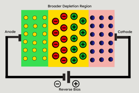
- Photoconductive Mode (Reverse Bias):
- In this mode, the photodiode is reverse-biased, meaning a voltage is applied in the opposite direction of the forward current.
- Reverse bias increases the width of the depletion region, reducing the capacitance and improving the response time.
- This mode is used in applications requiring fast response times and higher sensitivity, such as optical communication systems and high-speed photodetectors.
Photodiode Arrays
A photodiode array consists of multiple photodiodes arranged in a matrix configuration. These arrays are used for imaging and light detection applications where spatial resolution is important.
- Linear Arrays: Used in scanners and spectrometers, they consist of a single row of photodiodes.
- Two-Dimensional Arrays: Used in digital cameras and medical imaging, these arrays have multiple rows and columns of photodiodes to capture images.
Advantages of photodiode arrays include high sensitivity, fast response times, and the ability to detect light at multiple points simultaneously.

Join students and professionals
from across the world increasing their knowledge of Electrical Engineering.
One email at a time
We never send spam or give your information to anyone, Privacy Policy here.
Photodiode Circuits
Photodiode circuits are designed to amplify and process the electrical signal generated by the photodiode. Common circuit configurations include:
- Current-to-Voltage Converter (Transimpedance Amplifier):
- A transimpedance amplifier converts the current output of a photodiode into a corresponding voltage.
- It uses an operational amplifier (op-amp) with a feedback resistor to achieve this conversion.
- Example: In optical fiber communication, a photodiode coupled with a transimpedance amplifier converts the light signal into a voltage signal for further processing.
- Photovoltaic Mode Circuit:
- In this simple circuit, the photodiode is connected to a load resistor, and the voltage across the resistor is measured.
- This setup is common in light meters and solar cells.
- High-Speed Photodetector Circuit:
- For high-speed applications, a photodiode is reverse-biased and connected to a low-noise, high-speed op-amp.
- Example: In optical communication systems, this configuration allows for the rapid detection of optical signals.
Examples of Photodiode Circuits
- Simple Light Meter:
   - Photodiode connected in series with a resistor.
   - Voltage measured across the resistor indicates the light intensity.
- Transimpedance Amplifier Circuit:
   - Photodiode anode connected to the inverting input of an op-amp.
   - Feedback resistor (Rf) connected between the op-amp output and the inverting input.
   - The non-inverting input of the op-amp connected to the ground.
- Output voltage (Vout) = - (Photocurrent * Rf)- High-Speed Optical Receiver:
-Reverse-biased photodiode connected to the input of a high-speed op-amp.
-The op-amp amplifies the small current pulses generated by the photodiode.
-This setup is used in high-speed data communication.
Conclusion
Photodiodes are versatile components crucial for converting light into electrical signals. Understanding their operation, biasing methods, and circuit integration is essential for designing efficient light detection and measurement systems. Whether used individually or in arrays, photodiodes find applications across various fields, from simple light meters to complex optical communication systems.