A Class D amplifier is a type of audio amplifier that operates by switching on and off the output devices (usually transistors) at a high frequency, rather than amplifying the input signal in a linear fashion like Class A, B, or AB amplifiers. This switching operation allows Class D amplifiers to achieve high efficiency, often greater than 90%, which makes them ideal for applications where power efficiency and heat dissipation are critical.
Applications of Class D Amplifiers
- Portable Audio Devices: Due to their high efficiency and compact size, Class D amplifiers are commonly used in portable audio devices like smartphones, tablets, and Bluetooth speakers.
- Car Audio Systems: Class D amplifiers are used in car audio systems to provide high power output with minimal heat generation, allowing them to be used in confined spaces without the need for large heatsinks.
- Home Audio Systems: They are used in home theater systems and powered subwoofers, where high power and efficiency are required to drive large speakers.
- Professional Audio Equipment: Class D amplifiers are also found in professional audio equipment, such as PA systems and musical instrument amplifiers, where high power output and efficiency are essential.
- Telecommunications and RF Systems: Class D amplifiers can be used in telecommunications systems, where efficient amplification of signals is required.
Why Class D Amplifiers are Used
- High Efficiency: Class D amplifiers can achieve efficiency levels of over 90%, significantly reducing power loss in the form of heat, making them suitable for battery-powered devices and applications requiring efficient power usage.
- Compact Size: The high efficiency of Class D amplifiers means they require smaller heatsinks and cooling systems, allowing for more compact designs compared to other amplifier classes.
- Low Heat Dissipation: Since less power is wasted as heat, Class D amplifiers generate less heat, reducing the need for large cooling systems and improving the longevity of the components.
- High Power Output: Class D amplifiers can deliver high power to speakers without requiring large and heavy transformers, making them suitable for applications where weight and size are critical factors.
Circuit Diagram of a Class D Amplifier
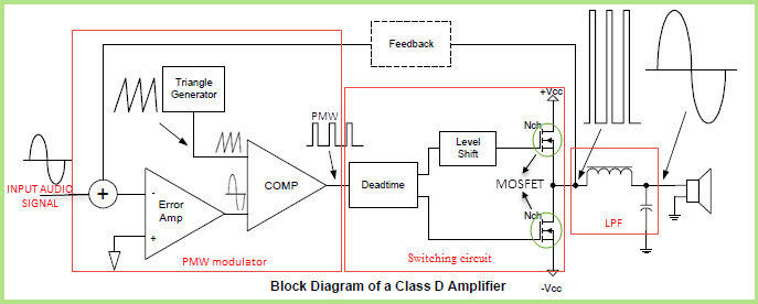
A typical Class D amplifier circuit consists of the following key components:
- Input Signal: The audio input signal that needs to be amplified.
- Pulse Width Modulator (PWM): Converts the input audio signal into a pulse-width modulated signal, where the duty cycle of the pulses corresponds to the amplitude of the audio signal.
- Switching Transistors: Typically MOSFETs, these transistors are switched on and off at a high frequency (usually in the range of hundreds of kHz to a few MHz) by the PWM signal.
- Low-Pass Filter: A passive LC (inductor-capacitor) filter that removes the high-frequency switching components, leaving only the amplified audio signal.
- Output: The filtered, amplified audio signal is sent to the speaker or load.
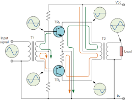
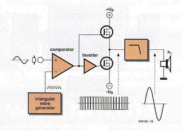
Here’s a simplified block diagram of a Class D amplifier:
The following is also a block diagram of a Class D amplifier with in more details:
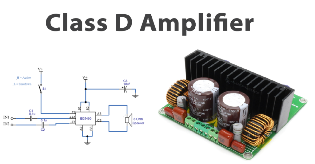
Here’s a simplified circuit diagram:
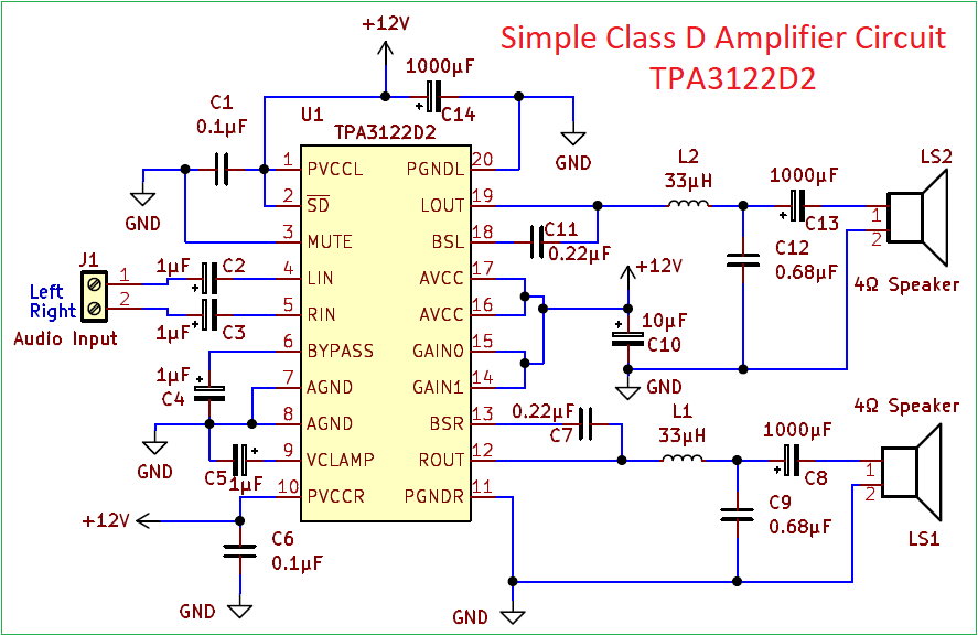
You can find the full details of the operation of the above circuit diagram including the downloadable Printed Circuit Board (PCB) Layout and all the list of items used here: https://theorycircuit.com/audio/simple-class-d-audio-amplifier-circuit/
Waveforms of a Class D Amplifier
- Input Signal: The input signal is a continuous analog waveform (e.g., a sinusoidal audio signal).
- PWM Signal: The pulse-width modulated signal consists of a series of pulses where the width of each pulse varies according to the amplitude of the input signal. The frequency of this PWM signal is much higher than the frequency of the input signal.
- Switching Waveform: The switching transistors generate a square wave corresponding to the PWM signal. These square waves switch between the supply voltage and ground at a high frequency.
- Filtered Output Signal: After the low-pass filter, the high-frequency components are removed, resulting in a waveform that closely resembles the original analog input signal but amplified.
The waveforms would look like this:
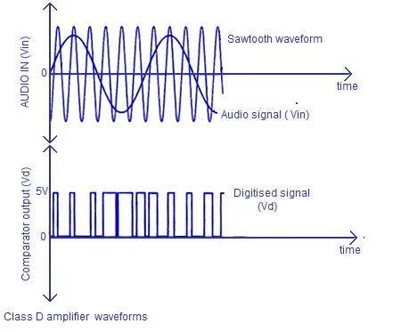
- Input Signal: A smooth sine wave (analog).
- PWM Signal: A series of variable-width pulses corresponding to the sine wave.
- Switching Waveform: A square wave switching between two voltage levels.
- Filtered Output Signal: A larger amplitude sine wave resembling the input signal.
For a deeper understanding of this Class of Amplifiers, there’s also an article specifically dealing with the comparison between Class D and Class AB amplifiers here.
Grab your very own Class D Amplifier and set up a powerful 2 x 30W Amplifier for your own home theatre. Watch the following video to see how:
Conclusion
Class D amplifiers are widely used due to their high efficiency, low heat dissipation, and compact size, making them ideal for a range of applications from portable devices to high-power audio systems. The combination of pulse-width modulation, high-frequency switching, and low-pass filtering allows Class D amplifiers to efficiently amplify signals while maintaining good audio quality.
Ready to take a dive into Electrical Engineering to get a head start on College or University, or simply expand your DIY knowledge?
Check out our meticulously designed course in Electrical/Electronic Engineering for all walks of life, from any country. Delivered by Professor F. Tavassoli.

Join students and professionals
from across the world increasing their knowledge of Electrical Engineering.
One email at a time
We never send spam or give your information to anyone, Privacy Policy here.