The 555 timer IC is a versatile and widely used integrated circuit in electronics, renowned for its reliability and ease of use in various timing, pulse generation, and oscillator applications. Introduced by Signetics in 1972, the 555 timer has become a staple in both hobbyist and professional electronics. This article delves into the construction and functionality of the 555 timer, how to build a basic circuit using the IC, and key formulas related to its operation.
1. Overview of the 555 Timer IC
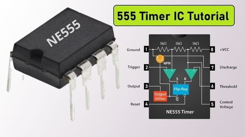
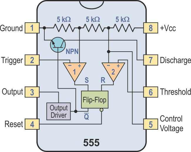
The 555 timer IC can operate in three modes: Astable, Monostable, and Bistable. The IC is housed in an 8-pin Dual In-line Package (DIP) and consists of two voltage comparators, a flip-flop, a discharge transistor, and a resistive voltage divider network.
Pin Configuration:
- Pin 1 (GND): Ground reference voltage, typically connected to 0V.
- Pin 2 (TRIG): Trigger input, where a negative pulse triggers the timer.
- Pin 3 (OUT): Output, which delivers the timer’s output signal.
- Pin 4 (RESET): Resets the timer when connected to ground.
- Pin 5 (CTRL): Control voltage, used for modulating the threshold voltage (typically connected to a capacitor for noise filtering).
- Pin 6 (THRES): Threshold input, used to monitor the voltage level.
- Pin 7 (DISCH): Discharge pin, connected to a capacitor to discharge it between cycles.
- Pin 8 (VCC): Supply voltage, typically 5V to 15V.
2. Building a 555 Timer Circuit
Let’s explore how to build a simple astable multivibrator circuit using the 555 timer. The astable mode is commonly used for generating a continuous square wave output.
Components Required:
- 1 x 555 Timer IC
- 1 x 10 kΩ Resistor (R1)
- 1 x 100 kΩ Resistor (R2)
- 1 x 1 µF Capacitor (C1)
- 1 x 0.01 µF Capacitor (C2, optional for noise reduction)
- 1 x LED (optional)
- 1 x 330 Ω Resistor (for the LED)
- Breadboard and connecting wires
- Power supply (5V)
Circuit Diagram:
Steps:
- Connect Pin 1 to the ground rail on the breadboard.
- Connect Pin 8 to the positive rail of the power supply.
- Place a 10 kΩ resistor (R1) between Pins 7 and 8.
- Place a 100 kΩ resistor (R2) between Pins 6 and 7.
- Place a 1 µF capacitor (C1) between Pins 6 and 1 (ground).
- Connect Pin 2 directly to Pin 6.
- Add an optional 0.01 µF capacitor (C2) between Pin 5 and ground to stabilize the voltage.
- Connect Pin 4 to the positive rail to avoid resetting the timer.
- Connect an LED with a 330 Ω resistor in series between Pin 3 (output) and ground.
3. Understanding the 555 Timer Functionality
Astable Mode:
In the astable mode, the 555 timer continuously oscillates between its high and low states, generating a square wave. The frequency and duty cycle of this oscillation are determined by the resistors R1, R2, and capacitor C1.
Operation:
- Initially, the capacitor C1 starts charging through resistors R1 and R2.
- When the voltage across C1 reaches 2/3 of the supply voltage, the upper comparator triggers, causing the output to go low, and the discharge transistor connected to Pin 7 turns on.
- The capacitor then discharges through R2 and the discharge pin.
- Once the voltage drops to 1/3 of the supply voltage, the lower comparator triggers, causing the output to go high, and the cycle repeats.
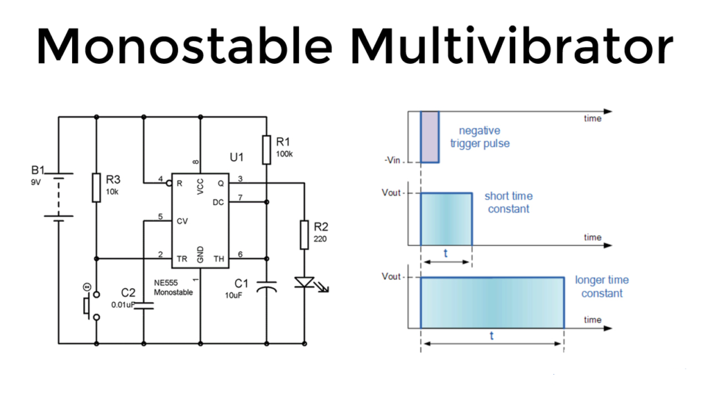
Monostable Mode:
In monostable mode, the 555 timer operates as a one-shot pulse generator. When triggered, it outputs a pulse of a specific duration before returning to its idle state. The duration of the pulse is determined by the resistor and capacitor connected to the timer.
Bistable Mode:
In bistable mode, the 555 timer works as a flip-flop, where the output is either high or low, depending on the state of the trigger and reset pins. It’s useful in applications requiring a basic memory element or toggle switch.
4. Key Formulas and Equations
In the astable mode, the frequency (f) and duty cycle (D) of the output waveform are given by the following formulas:
Where:
- ( R1 ) and ( R2 ) are the resistances in ohms (Ω)
- ( C1 ) is the capacitance in farads (F)

The duty cycle represents the proportion of the time the output is high (in percentage).
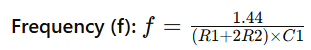
In monostable mode, the pulse width (T) is determined by the formula:
Pulse Width (T):

Where:
- ( T ) is the duration of the pulse in seconds (s)
- ( R1 ) is the resistance in ohms (Ω)
- ( C1 ) is the capacitance in farads (F)
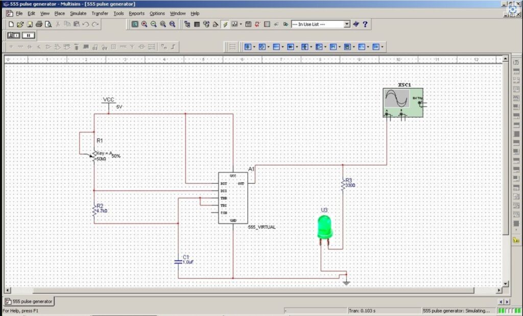
In this video I show you how to build and simulate a 555 timer in Multisim.
5. Applications of the 555 Timer
The versatility of the 555 timer allows it to be used in a wide range of applications, including:
- Square Wave Generators: Used in signal processing and clock pulse generation.
- Pulse Width Modulation (PWM): Commonly used in motor control and dimming LEDs.
- Timers and Delay Circuits: Creating precise time delays or intervals.
- Tone Generators: Producing audio tones in alarms or simple sound effects.
- Schmitt Trigger Circuits: Converting noisy signals into clean digital ones.
6. Conclusion
The 555 timer IC remains a fundamental building block in electronics, offering simplicity and flexibility for a myriad of applications. Whether you’re designing a simple LED flasher or a more complex pulse-width modulation circuit, understanding the construction, operation, and key formulas of the 555 timer is essential. With its robust design and ease of use, the 555 timer continues to be a go-to component for engineers and hobbyists alike.
By following the guidelines provided in this article, you should be able to effectively utilize the 555 timer IC in various projects, harnessing its full potential to create innovative electronic solutions.
Ready to take a dive into Electrical Engineering to get a head start on College or University, or simply expand your DIY knowledge?
Check out our meticulously designed course in Electrical/Electronic Engineering for all walks of life, from any country. Delivered by Professor F. Tavassoli.
Join students and professionals
from across the world increasing their knowledge of Electrical Engineering.
One email at a time
We never send spam or give your information to anyone, Privacy Policy here.