Understanding Class A Transistor Amplifiers: An In-Depth Overview
Introduction
Class A transistor amplifiers are a fundamental component in the world of electronics, playing a crucial role in various applications. Known for their simplicity and linearity, these amplifiers are widely used in audio, radio frequency (RF) applications, and other precision amplification scenarios. This article delves into the workings of Class A transistor amplifiers, exploring their usage, applications, advantages, and disadvantages.
What is a Class A Transistor Amplifier?
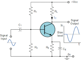
A Class A transistor amplifier is a type of amplifier where the output current flows continuously during the entire input signal cycle. This means that the transistor conducting the amplification operates in the active region throughout the entire cycle, which results in high linearity and low distortion. The basic design typically consists of a single transistor, resistor, and a power supply.
In a Class A amplifier, the transistor is biased in such a way that it remains on for the entire period of the input signal. This continuous operation makes Class A amplifiers capable of providing high-fidelity amplification, making them ideal for applications requiring precise signal reproduction.
Why and Where Are Class A Amplifiers Used?
1. Audio Amplification:
Class A amplifiers are highly regarded in the audio industry for their superior sound quality. Their ability to produce a linear output with minimal distortion makes them ideal for high-end audio equipment, such as home audio systems, professional studio monitors, and guitar amplifiers. Audiophiles often prefer Class A amplifiers because they faithfully reproduce the nuances and details of the original sound.
2. Radio Frequency (RF) Amplification:
In RF applications, where signal integrity is paramount, Class A amplifiers are often used. Their linearity ensures that the amplified RF signals maintain their original waveform, reducing the risk of signal distortion that could lead to interference or degradation of communication quality.
3. Precision Instrumentation:
Class A amplifiers are also used in precision instrumentation, where accurate signal amplification is critical. Their low distortion characteristics make them suitable for applications such as analog signal processing, sensor signal conditioning, and scientific measurement equipment.
Applications of Class A Transistor Amplifiers
- High-Fidelity Audio Systems: Class A amplifiers are used in high-end audio systems, where sound quality is prioritized over efficiency. They are often found in pre-amplifiers and power amplifiers for audiophiles who seek the best possible audio experience.
- Broadcast Transmitters: Due to their linearity, Class A amplifiers are used in broadcast transmitters, where maintaining signal purity is essential for clear and reliable transmission.
- Laboratory and Test Equipment: Precision amplifiers in laboratory settings often utilize Class A designs to ensure accurate signal amplification with minimal distortion.
- Guitar Amplifiers: Musicians, particularly guitarists, prefer Class A amplifiers for their warm, rich sound, which is a result of the amplifier’s ability to produce even-order harmonics.
Pros of Class A Transistor Amplifiers
- High Linearity: Class A amplifiers offer excellent linearity, meaning the output signal is a faithful reproduction of the input, with minimal distortion. This makes them ideal for applications where signal fidelity is crucial.
- Low Distortion: The continuous operation of the transistor in the active region ensures that Class A amplifiers produce very low levels of harmonic distortion, leading to cleaner and more accurate amplification.
- Simplicity: The design of Class A amplifiers is straightforward, with a single transistor handling the amplification. This simplicity can be an advantage in terms of reliability and ease of construction.
- Consistent Performance: Since the transistor is always conducting, the amplifier’s performance remains consistent regardless of the input signal level, providing stable operation.
Cons of Class A Transistor Amplifiers
- Inefficiency: One of the major drawbacks of Class A amplifiers is their inefficiency. Since the transistor is always on, even when no input signal is present, the amplifier consumes a significant amount of power, with most of it being dissipated as heat. This can lead to power inefficiency, especially in high-power applications.
- Heat Generation: The continuous operation of the transistor leads to significant heat generation. Adequate heat management, such as heat sinks or cooling fans, is required to prevent overheating and ensure long-term reliability.
- Limited Power Output: Class A amplifiers are generally not suitable for high-power applications due to their inefficiency. Their design constraints often limit them to low or moderate power levels, which may not be sufficient for some high-power amplification needs.
- Size and Cost: The need for heat management and power supplies capable of handling the constant current draw can make Class A amplifiers bulkier and more expensive compared to other amplifier classes.
Summary of Class A Amplifiers
Class A transistor amplifiers are a key component in applications where signal fidelity and low distortion are paramount. Their superior linearity and simplicity make them the amplifier of choice for high-end audio equipment, RF amplification, and precision instrumentation. However, their inefficiency and heat generation are significant drawbacks that must be considered, particularly in applications requiring higher power output or energy efficiency.
Despite these limitations, Class A amplifiers continue to hold a special place in the hearts of audiophiles and engineers who prioritize sound quality and signal accuracy above all else. Understanding the pros and cons of Class A amplifiers allows engineers and designers to make informed decisions about their use in various electronic applications.
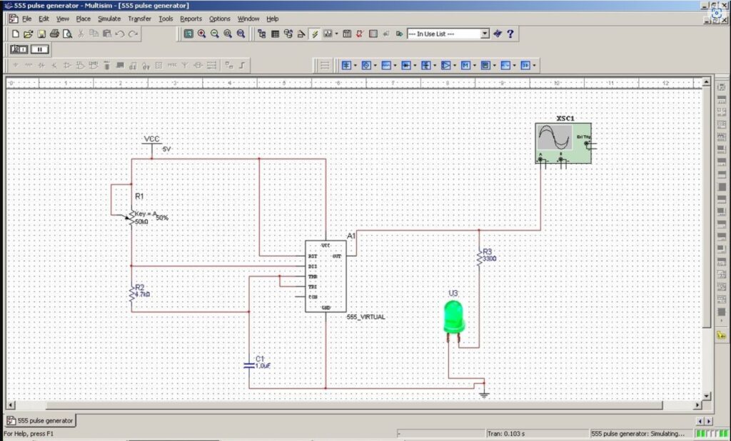
Watch me build a single stage class A amplifier from scratch on Multisim and see how I eliminate all the problems during the building and testing of the circuit, then get the final simulation results shown on the virtual oscilloscope here:
And Now onto Class B Amplifiers
Class B Amplifiers: Detailed Overview, Applications, and Analysis
Introduction to Class B Amplifiers
Class B amplifiers are a fundamental type of power amplifier widely used in various electronic devices. Unlike Class A amplifiers, which conduct over the entire input signal cycle, Class B amplifiers conduct over half of the input signal, making them more efficient. This article provides a comprehensive overview of Class B amplifiers, including their operation, applications, advantages, and disadvantages.
How Class B Amplifiers Work
Class B amplifiers operate by splitting the input signal into two halves: the positive half-cycle and the negative half-cycle. Two transistors are typically used, one for each half of the signal. The transistors conduct alternately, with one transistor amplifying the positive half and the other amplifying the negative half.
Diagram of a Basic Class B Amplifier Circuit
Here’s a simplified diagram of a Class B amplifier:
In this configuration:
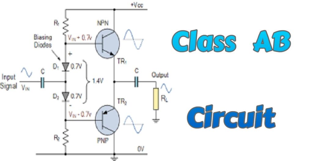
- TR1 is an NPN transistor that conducts when the input signal is positive.
- TR2 is a PNP transistor that conducts when the input signal is negative.
- The transistors are arranged in a Push-Pull configuration, where Q1 amplifies the positive half of the waveform, and Q2 amplifies the negative half.
As explained the above circuit diagram is designed in a Push-Pull configuration, which means each half a cycle, one transistor is turned on, and one transistor is turned off, which also helps in cooling down the transistors as they’re not constantly in use.
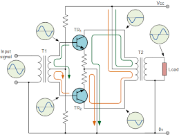
The same Push-Pull configuration can be arranged using two transistors of the same type, but with the help of a mid point transformer, which turns the incoming signal into two signals of 180 degree opposite phases as shown in the following diagram where both transistors used are NPN type.
Why Use Class B Amplifiers?
Class B amplifiers are favored in many applications due to their efficiency. Since each transistor only conducts for half of the input signal, they consume less power and generate less heat compared to Class A amplifiers. This makes them ideal for battery-powered devices and applications where energy efficiency is critical.
Applications of Class B Amplifiers
Class B amplifiers are commonly used in the following applications:
- Audio Amplifiers: Class B amplifiers are often used in audio power amplification stages where efficiency is important, such as in battery-powered audio devices.
- Radio Frequency (RF) Transmitters: The efficiency of Class B amplifiers makes them suitable for RF transmitters, where power consumption is a major concern.
- Signal Processing: In some signal processing circuits, Class B amplifiers are used where linearity is not the primary requirement.
- Public Address Systems: These amplifiers are often used in PA systems, where efficiency and the ability to drive large speakers are necessary.
Pros of Class B Amplifiers
- High Efficiency: Class B amplifiers have a higher efficiency (up to 78.5%) compared to Class A amplifiers, making them suitable for applications where power efficiency is essential.
- Lower Heat Dissipation: Because only one transistor conducts at a time, less power is wasted as heat, reducing the need for large heatsinks.
- Cost-Effective: Due to their simpler design and fewer components, Class B amplifiers are often more cost-effective to produce.
Cons of Class B Amplifiers
- Crossover Distortion: One of the major disadvantages of Class B amplifiers is crossover distortion, which occurs at the point where the signal transitions from the positive half-cycle to the negative half-cycle. This can lead to a noticeable distortion in the output signal, especially in audio applications.
- Complex Biasing: To minimize crossover distortion, precise biasing is required, which can add complexity to the design.
- Limited Linearity: Class B amplifiers are less linear than Class A amplifiers, making them less suitable for applications requiring high fidelity.
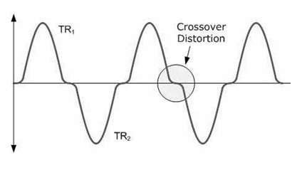
Diagram: Crossover Distortion in Class B Amplifiers
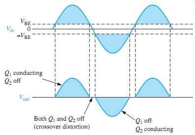
The reason the crossover distortion occurs is due to the voltage between Base and Emitter of the transistor that needs to rise to the minimum bias voltage to bias the transistor and break through the depletion region of the Base Emitter diode part of the transistor, so until the voltage reaches that value, which is about 0.6-0.8 volts depending on the transistor, the transistor is off, and so there will be nothing amplified, hence you have the crossover distortion effect as seen in the above diagram and the following more detailed waveform.
Here is a visual representation of crossover distortion:
The following shows when the crossover distortion occurs in respect to the voltage of the Base-Emitter of each transistor.
Mitigating Crossover Distortion
To reduce crossover distortion, a small bias voltage is applied to the transistors to ensure that they conduct slightly even when the input signal is near zero. This configuration is known as a Class AB amplifier, which combines the efficiency of Class B with the linearity of Class A.
Summary of Class B Amplifiers
Class B amplifiers offer a good balance between efficiency and performance, making them suitable for a wide range of applications, especially where power efficiency is crucial. However, they are not without their drawbacks, particularly regarding crossover distortion. Engineers must carefully consider these trade-offs when designing circuits that incorporate Class B amplifiers. In situations where crossover distortion is a critical concern, a Class AB amplifier may be a better alternative.
Understanding the operation, benefits, and limitations of Class B amplifiers is essential for anyone working with power amplification circuits, whether in audio, RF, or other signal processing applications.
Watch me here build a Class B amplifier from scratch on Multisim and see how I eliminate noise and other issues during the building and simulating the circuit, and finally get the desired results on the virtual oscilloscope.
Summary Conclusion – Comparison between Class A and Class B Amplifiers
- Class A amplifiers are preferred in applications where sound quality is paramount, despite their inefficiency and heat generation.
- Class B amplifiers are used where efficiency and power output are more critical than audio fidelity, making them suitable for applications like PA systems and certain RF amplifications.
To balance the pros and cons of these designs, hybrid amplifiers like Class AB are often used, combining the low distortion of Class A with the higher efficiency of Class B.
Ready to take a dive into Electrical Engineering to get a head start on College or University, or simply expand your DIY knowledge?
Check out our meticulously designed course in Electrical/Electronic Engineering for all walks of life, from any country. Delivered by Professor F. Tavassoli.
Join students and professionals
from across the world increasing their knowledge of Electrical Engineering.
One email at a time
We never send spam or give your information to anyone, Privacy Policy here.