Their Applications, Measurement, and Calculation
What is a High Pass Filter?
A high pass filter (HPF) is an electronic circuit that allows signals with a frequency higher than a certain cutoff frequency to pass through while attenuating signals with frequencies lower than this cutoff. This type of filter is essential in many electronic applications, including audio processing, communication systems, and signal conditioning.
Applications of High Pass Filters
- Audio Systems: In audio processing, high pass filters are used to eliminate low-frequency noise or hum from audio signals. For example, they can remove rumble from vinyl records or unwanted bass frequencies from recordings.
- Communication Systems: In radio and television broadcasting, HPFs help in filtering out low-frequency interference and noise, ensuring clearer signal transmission and reception.
- Signal Conditioning: HPFs are used in measurement and instrumentation systems to filter out low-frequency drift and noise, improving the accuracy of measurements.
- Analog-Digital Conversion: In ADC systems, high pass filters can remove low-frequency components that might cause aliasing or affect the performance of the converter.

Components of a High Pass Filter
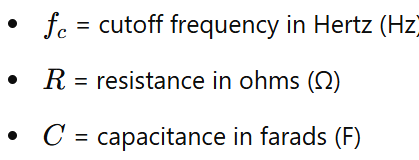
- Capacitor (C): Blocks low-frequency signals and allows high-frequency signals to pass through.
- Resistor (R): Works in conjunction with the capacitor to set the cutoff frequency of the filter.
Calculating the Cutoff Frequency

The formula to calculate the cutoff frequency is:
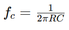
where:
Measuring the Cutoff Frequency Using an Oscilloscope
To measure the cutoff frequency of a high pass filter using an oscilloscope, follow these steps:
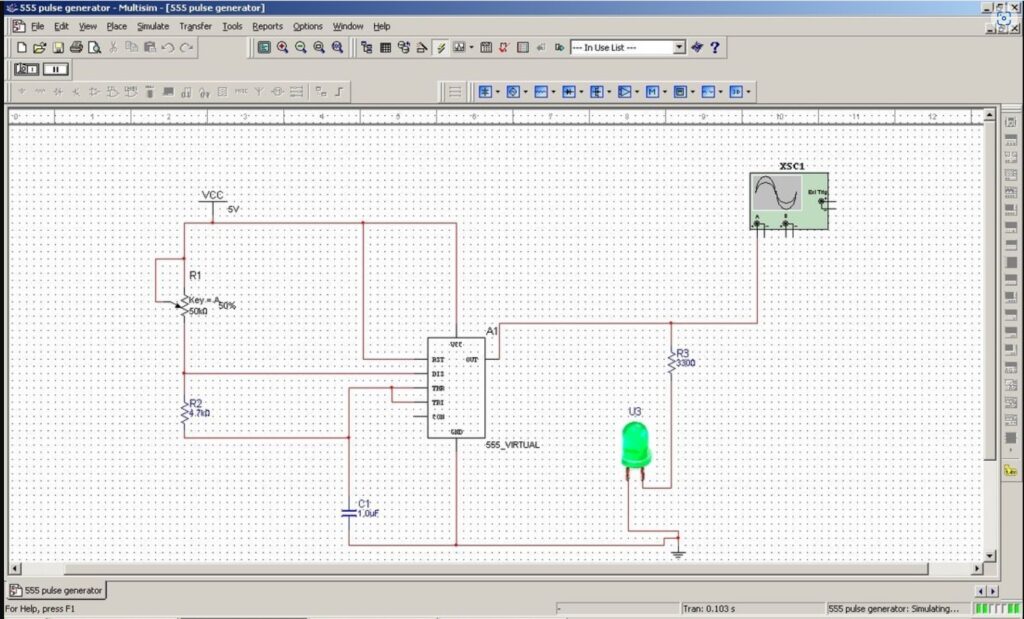
- Setup the Circuit: Connect the high pass filter circuit to the oscilloscope. Ensure that the input signal is a sine wave with a frequency that spans a range including the expected cutoff frequency.
- Apply a Signal: Use a signal generator to apply a sine wave input to the filter. Start with a frequency much lower than the expected cutoff frequency and gradually increase it.
- Observe the Output: On the oscilloscope, observe the amplitude of the output signal. At frequencies well below the cutoff, the output should be significantly attenuated. As the frequency approaches the cutoff, the output amplitude will begin to increase.
- Determine the Cutoff Frequency: Identify the frequency at which the output signal’s amplitude drops to approximately 70.7% of the input signal amplitude. This frequency is the cutoff frequency of the filter.
- Verification: For accuracy, verify the measurement by comparing it with the calculated cutoff frequency using the formula provided. Adjust the circuit components if necessary and remeasure.
Example Calculation
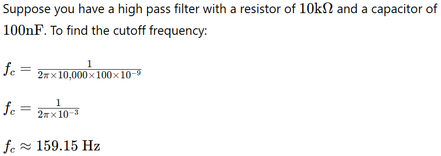
So, the cutoff frequency is approximately 159 Hz.
In practice, you would apply a signal and use an oscilloscope to confirm that the output signal amplitude begins to attenuate around this frequency.
Conclusion
High pass filters are fundamental components in electronic circuits, enabling the selective passing of high-frequency signals while blocking lower frequencies. By understanding their operation and accurately measuring the cutoff frequency, engineers can design and implement effective filters for a wide range of applications.
Ready to take a dive into Electrical Engineering to get a head start on College or University, or simply expand your DIY knowledge?
Check out our meticulously designed course in Electrical/Electronic Engineering for all walks of life, from any country. Delivered by Professor F. Tavassoli.

Join students and professionals
from across the world increasing their knowledge of Electrical Engineering.
One email at a time
We never send spam or give your information to anyone, Privacy Policy here.