Understanding Low-Pass Filters: A Comprehensive Guide
Low-pass filters (LPFs) are fundamental components in electronics and signal processing, used to allow low-frequency signals (i.e. signals with frequencies lower than a certain cutoff frequencies) to pass through while attenuating higher-frequency signals. This article delves into the principles of low-pass filters, their applications, and provides some sample diagrams and oscilloscope waveforms to illustrate their operation.
What is a Low-Pass Filter?
A low-pass filter is a circuit that passes signals with a frequency lower than a certain cutoff frequency and attenuates signals with frequencies higher than this cutoff. The rate of attenuation depends on the design of the filter. LPFs are widely used in various applications, such as audio processing, communication systems, and analog-to-digital conversion.
Basic Types of Low-Pass Filters
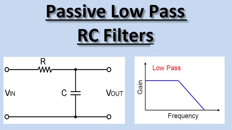
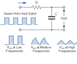
1. Passive Low-Pass Filter:
- Components: Typically consists of a resistor (R) and a capacitor (C).
- Operation: The capacitor blocks high-frequency signals while allowing low-frequency signals to pass.
- Cutoff Frequency (f_c): Given by the formula
- Circuit Diagram:
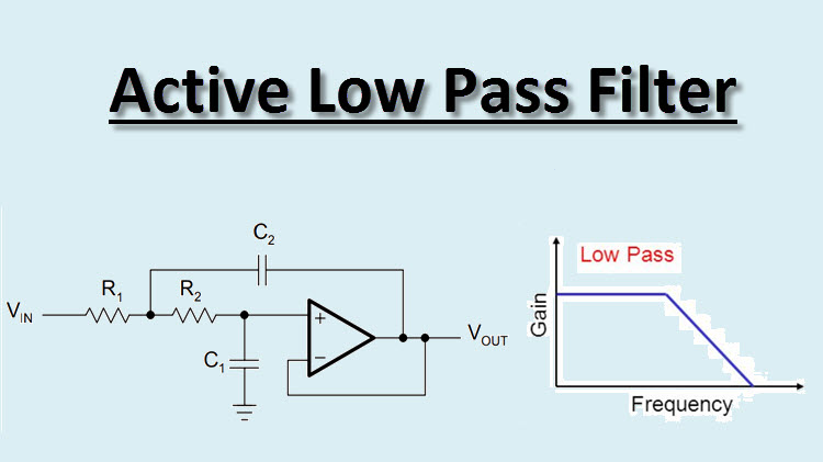
2. Active Low-Pass Filter:
- Components: Includes operational amplifiers (op-amps) along with resistors and capacitors.
- Operation: Provides amplification in addition to filtering, which can be useful in applications requiring a stronger signal.
- Circuit Diagram:
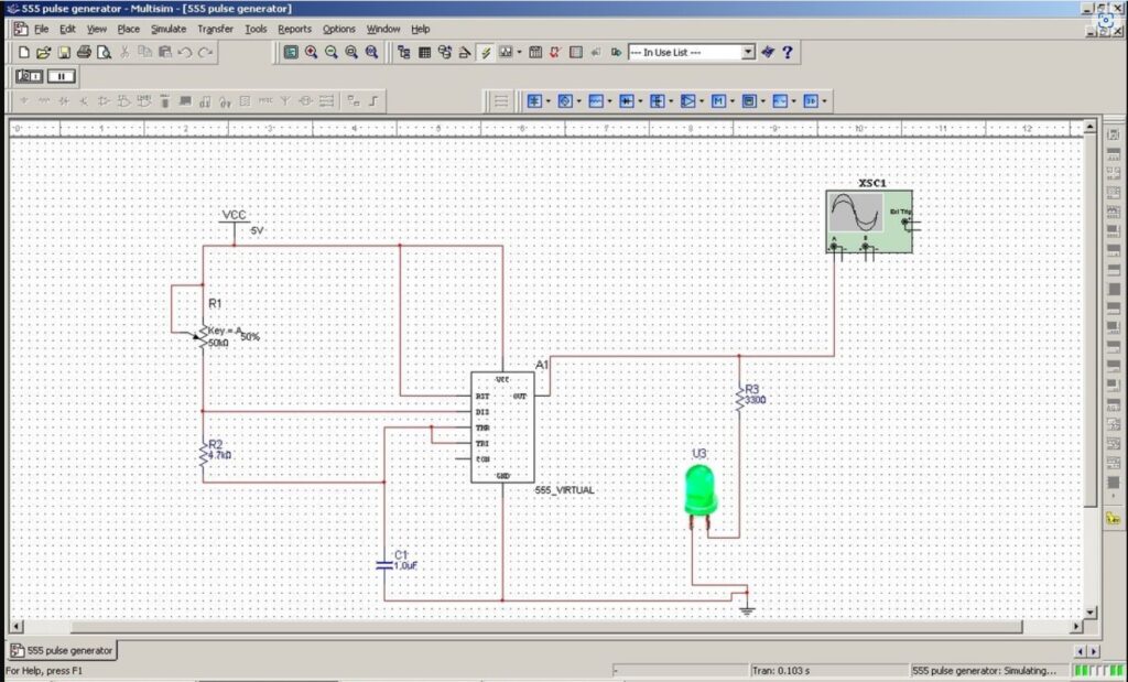
Watch me in the following video build and explain the operation of an R-C Low Pass Filter using Multisim;
Calculating / Measuring the Cutoff Frequency
Cutoff Frequency Formula
The cutoff frequency (f_c) of an RC low pass filter can be calculated using the following formula:
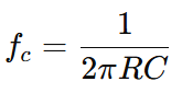
R is the resistance in ohms (Ω).
C is the capacitance in farads (F).
f_c is the cutoff frequency in hertz (Hz).
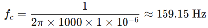
For example, if you have a resistor of 1 kΩ and a capacitors of 1 µF, the cutoff frequency would be:
Measuring the Cutoff Frequency Using an Oscilloscope
To measure the cutoff frequency using an oscilloscope, follow these steps:
- Set Up the Circuit: Construct the RC low pass filter circuit with known values of R and C.
- Input Signal: Apply a sinusoidal signal to the input of the low pass filter. Start with a low frequency and gradually increase it.
- Connect the Oscilloscope: Connect the oscilloscope probes across the output capacitor.
- Observe the Output: As you increase the input signal frequency, observe the output amplitude on the oscilloscope. The cutoff frequency is identified as the point where the output signal amplitude drops to 70.7% (or -3 dB) of its maximum value.
At the cutoff frequency, the output voltage (V_out) will be:
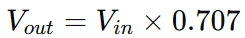
where ( Vin ) is the input signal amplitude.
Calculate the Cutoff Frequency: If using an oscilloscope with a frequency counter, you can directly read the frequency when the output voltage drops to 0.707 of its initial value. Otherwise, manually adjust the input frequency until the output amplitude matches the calculated Vout, and note the corresponding frequency
Watch me use a virtual oscilloscope to measure the cut off frequency on a simulated R-C low pass filter in Multisim below:
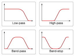
Frequency Response of a Low-Pass Filter
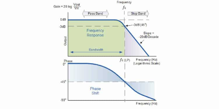
The frequency response of a low-pass filter is characterized by its ability to attenuate high-frequency signals while passing low-frequency signals. The key parameters are:
- Passband: The range of frequencies that are allowed to pass with minimal attenuation.
- Stopband: The range of frequencies that are significantly attenuated.
- Cutoff Frequency (f_c): The frequency at which the output signal is reduced to 70.7% of the input signal (3 dB point).
Frequency Response Curve:
- The frequency response curve of a low-pass filter typically shows a flat response at low frequencies, followed by a gradual drop-off at the cutoff frequency, leading into the stopband.
Oscilloscope Waveforms
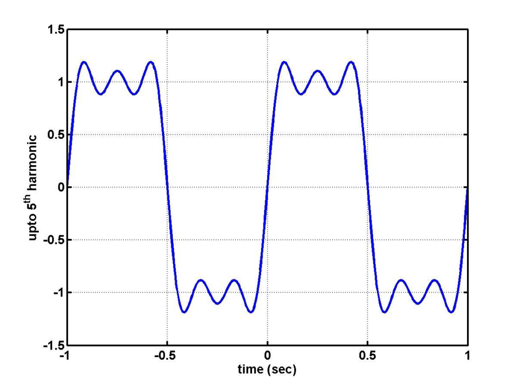
To visualize how a low-pass filter works, let’s consider an example where the input signal is a square wave containing multiple frequency components.
- Input Signal (Square Wave):
Waveform: The square wave has sharp transitions, indicating the presence of high-frequency components.
- Output Signal after Passing Through a Low-Pass Filter:
Waveform: The output signal is a smoothed version of the square wave. High-frequency components are attenuated, leaving the low-frequency components, resulting in a more sinusoidal waveform.
Oscilloscope Display:
Explanation: As the filter attenuates the higher frequencies, the sharp edges of the square wave are rounded off, resulting in a waveform that more closely resembles a sine wave, which has only the fundamental frequency component.
Applications of Low-Pass Filters
- Audio Processing:
Low Pass Filters are used in audio systems to remove high-frequency noise from audio signals, ensuring that only the desired lower frequencies are heard.
- Data Smoothing:
In data acquisition systems, Low Pass Filters smooth out high-frequency noise in sensor signals, providing cleaner data for further processing.
- Communication Systems:
Low Pass Filters are crucial in demodulation circuits to extract the original information signal from a modulated carrier wave by filtering out high-frequency components.
- Audio Processing:
Low pass filters are widely used in audio systems to remove high-frequency noise or to separate different bands of audio frequencies. For example, in a speaker system, an LPF is used to direct low-frequency signals to a subwoofer.
- Signal Conditioning:
In data acquisition systems, low pass filters are employed to eliminate high-frequency noise from the measured signals, ensuring accurate readings.
- Telecommunications:
LPFs are used in communication systems to limit the bandwidth of signals to prevent interference and to improve the signal-to-noise ratio.
- Anti-Aliasing Filters:
In digital signal processing, low pass filters are used before analog-to-digital conversion to remove frequencies higher than half the sampling rate, preventing aliasing.
Conclusion
Low-pass filters are indispensable in various fields of electronics and signal processing. By allowing low-frequency signals to pass and attenuating high-frequency noise, they play a critical role in ensuring the integrity and clarity of signals in both analog and digital systems. Whether in audio engineering, communications, or instrumentation, understanding and utilizing low-pass filters is essential for effective signal management. Understanding how to calculate and measure the cutoff frequency of these filters is essential for designing circuits that effectively manage signal bandwidth and minimize noise. By using the formula provided and an oscilloscope, engineers and technicians can precisely determine the cutoff frequency to ensure optimal filter performance.
Note: The diagrams and oscilloscope wave forms in this article are simplified for illustrative purposes. For more detailed designs and visualizations, consider using simulation software or an actual oscilloscope to experiment with different filter configurations.